Combustor
Wiring the SmartPhone BMS
for a
Combustor
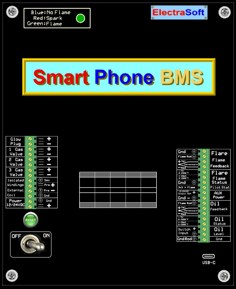
Connect Wires
Important - Before wiring:
- Set the [Power 12-24VDC] switch to OFF. This ensures the
BMS won’t react if any connected wire unexpectedly carries a signal.
- Verify that the power-supply and all other wires you plan to connect are
de-energized or isolated from live circuits.
Begin by mounting the BMS in a vertical, upright position with the buckles
on the right and the hinge on the left. Drill two holes at the
bottom; one on the right and one on the left.
When dressing the wires, consider both current and voltage characteristics.
Some wires carry high current, while others carry high
voltage, and improper proximity can lead to interference. In
particular, wires routed too closely; especially from opposite sides; can
behave like the primary winding of a transformer, inducing unwanted voltages
in adjacent conductors.
To minimize interference:
- Keep left-side and right-side wiring physically separated whenever possible.
- Avoid parallel runs of dissimilar signal types over long distances.
- Use shielding or twisted pairs for sensitive signal lines if necessary.
Route all wires from the peripherals back to the BMS, ensuring clean
alignment and proper strain relief. Securely terminate each wire into the
appropriate Phoenix connector, verifying polarity and
connection integrity.
Starting Bottom-Right to Top-Right:
Wire sizes are suggested minimums and may be increased as needed.
- Gnd, Gnd: Connect an 18AWG or heavier wire to the ground rod.
- Oil Level, Switch Input: May also appear as Process Ctl 1, Input.
This input is optional and can be configured to monitor gas pressure via a
4-20mA signal, representing 0-100% of the selected gas sensor range. If gas
pressure is below threshold during system check, the BMS will inhibit the burn
sequence to prevent unsafe ignition conditions.
- Oil Status, 4-20mA 0-2000°F: This input accepts a 4-20mA
signal representing temperatures from 0 to 2000°F. The measurement is read
between the connector and ground. It reflects the status of the
Oil Feedback, Thermocouple repurposed to Set Max Temp Shutdown °F
and can also interface with optional external equipment, such as wireless
transmitters or remote monitoring
systems.
- Oil Status, 1-5 V, 0-2000°F: This input operates similarly to the
4-20mA version, accepting a 1-5 V signal corresponding to temperatures from
0 to 2000°F. It reflects the status of the Oil Feedback, Thermocouple
repurposed to Set Max Temp Shutdown °F
and may also interface with optional equipment such as wireless transmitters
or remote monitors.
- Oil Feedback, Thermocouple: Repurposed as Set Max Temp
Shutdown °F, displayed in the event monitor as Combust CT Temp.
Connect the positive (+) wire to the yellow Phoenix connector
and the negative (-) wire to the red connector. For optimal
signal integrity, use a twisted pair or shielded cable,
grounded at both ends.
- Oil Feedback, Flame Rod: Third flame verification option. Identified
in configuration as Pilot: Oil Flame Rod and displayed in the event
monitor as Pilot Flame Rod Ion.
- AUX Power, Output AUX: Auxiliary power output for optional equipment
such as a radio or monitoring device. Voltage is derived from the main Power
Input (12-24VDC).
- Pilot Status, 3V3 = Flame: Indicates pilot flame presence. When no
flame is detected, this connector reads below 1V. When flame is
detected, based on your selected method, it will read approximately 3.3V.
- Flare Flame Status, Gnd: Serves as a local ground reference for
low-current wire connections within the flare flame status area. Use this
ground point to minimize interference from high-current eddies and prevent
signal distortion in nearby sensitive components.
- Flame Status, 4-20 mA, 0-2000°F: Current loop signal output
representing flame temperature feedback from the Flare Flame Feedback,
Thermocouple. This output can interface with optional external devices
such as radios or monitoring systems.
- Flame Status, 1-5V, 0-2000°F: Voltage-based input derived from
the above 4-20 A signal, typically achieved by applying a 250-ohm resistor
across the loop. Useful for systems preferring direct voltage signals or
simplified analog interfacing.
- Flare Flame Feedback, Thermocouple: This input serves as the first
flame verification option. In configuration, it appears as
Pilot: Thermocouple and is displayed in the event monitor as
Flare TC Temp.
- Flare Flame Feedback, Flame Rod: This input serves as the second
flame verification option. It is listed in the configuration as
Pilot: Flare Flame Rod and appears in the event monitor as
Flare Flame Rod Ion.
Starting Bottom-Left to Top-Left:
Where wire sizes may be suggested but can be heavier.
- Power, 12/24VDC: Connect the positive and negative leads from a
power supply to the Phoenix terminals using 18AWG or heavier wire.
- Isolated Windings External Coil: Ignition Option
- Gnd: Required only if using Ignition Electrode Ionization Feedback
for flame verification. Connect an 18AWG or larger wire from the spark
electrode's ground point to this Phoenix terminal, as close as possible to
where the spark lands.
- Prm-: Connect to the negative lead from the coil's primary winding.
- Prm+: Connect to the positive lead from the coil's primary winding.
- Sec: Used only when Ignition Electrode Ionization Feedback is
selected for flame verification. Connect a wire from the low side of the
ignition coil’s secondary winding to this Phoenix terminal. During ignition,
it completes the spark return path; between pulses, it carries the flame
ionization signal to the BMS, where flame presence is monitored.
- 3 Gas Valve: Unused (NC)
- 2 Gas Valve:Main Gas control. Wire identically to Gas Valve 3, with
activation managed by the BMS grounding the (-) terminal.
- 1 Gas Valve: Pilot Gas control. Same wiring configuration as Valves 2
and 3. Ensure polarity is correct and terminals are secure.
- Glow Plug: Ignition option. Connect the (+) and (-) leads to the
Glow Plug. The positive terminal remains constantly energized. Once the
Glow Plug is connected, voltage flows through it, elevating the (-) terminal
to the same potential as the (+). The BMS activates the Glow Plug by grounding
the (-) terminal, completing the circuit and energizing the heating
element.
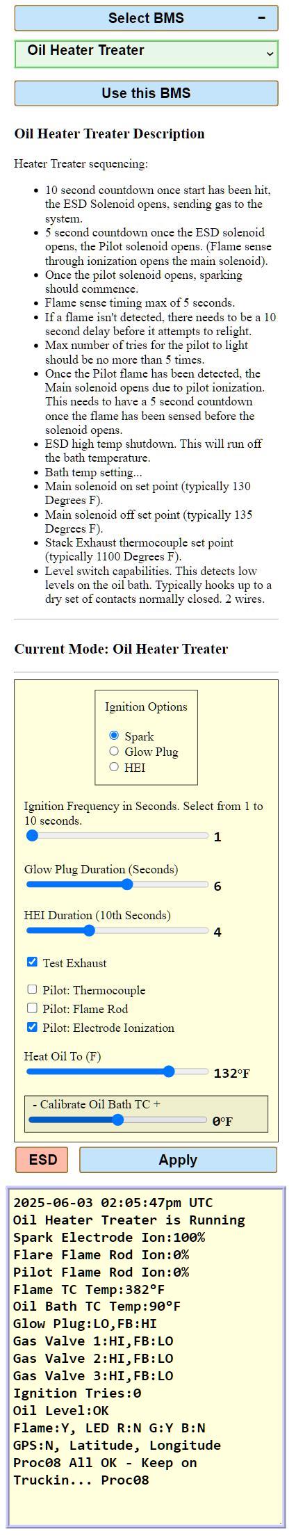
Configuring the Combustor
SmartPhone BMS Interface
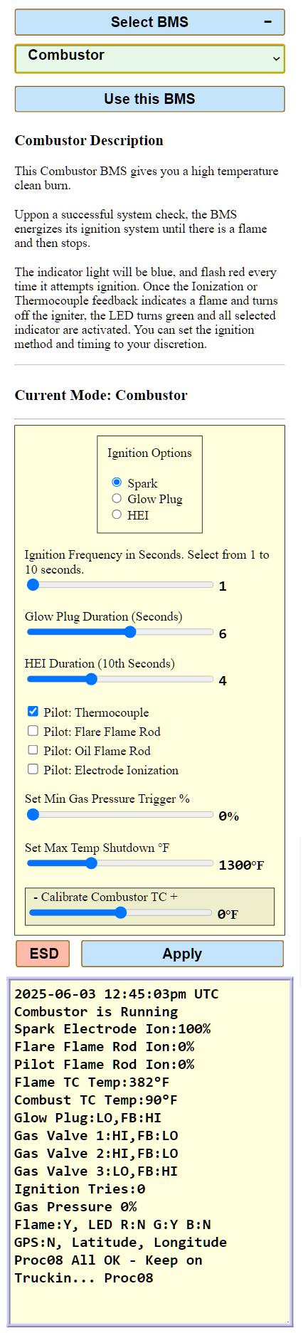
Configure the BMS
Use a SmartPhone and select Combustor and configure the BMS.
This section guides you through configuring ignition, and flame
detection settings for the Combustor.
Configuration Steps
- Ignition Options: Select: Spark, Glow Plug, or HEI.
- Ignition Frequency: Set interval (1-10 seconds). Example: If set to
1 second, the system will attempt ignition every second.
- Glow Plug Duration: Set duration in seconds. Example: If set to 6
seconds, the glow plug will stay energized for 6 seconds per cycle.
- HEI Duration: Set pulse length (tenths of seconds). Example: A
setting of 4 corresponds to 0.4 seconds.
- Pilot: Flame verification, select an options:
- Pilot: Thermocouple
- Pilot: Flare Flame Rod
- Pilot: Oil Flame Rod
- Pilot: Electrode Ionization
Example: If [Pilot: Electrode Ionization] is checked, the system will use this
method for flame verification.
- Set Min Gas Pressure Trigger %: Optional parameter. If unused,
set to 0%. This value appears in the event monitor as Gas Pressure,
and may be labeled on the BMS interface as Oil Level or alternatively
as Process Ctl 1.
- Set Max Temp Shutdown F: The Oil Feedback, Thermocouple:
is used here to monitor the exhaust temperature. If the temperature raises above
this set temperature the system will shutdown and wait for someone to find the
cause. will be seen in the event monitor as Combust TC Temp
- Calibrate Combustor TC: If the thermocouple reading is slightly off,
adjust it using the [- Calibrate Combustor TC +] slider.
- [ESD] /
[RUN]:
Dual-function button for Emergency Shutdown and Run modes.
- ESD/RUN Operation: Press
[ESD] to shut down;
it will switch to
[RUN].
Keep the system in shutdown mode during configuration.
- [Apply]:
Saves any changes to settings.
|


 Connectivity
 RoHS-compliant UL-certified NEMA 4X enclosures